|
<< Contents
<< Workbar
<< WorkBar Tabs
<< CHANNELS
|
| |
|
|
| |
|
The Glitch Detectors tab is displayed only when Glitch Timing mode is active.
|
| |
|
A "glitch" occurs when a signal transitions two or more times during one logic analyzer sample. For example, the logic analyzer provides 2 ns resolution when sampling at 500 MHz. A glitch is marked in the trace data any time a channel transitions two or more times period between each 2 ns sample. Glitch marks are displayed in the WaveForm view as a vertical line on the timing diagrams.
|
| |
|
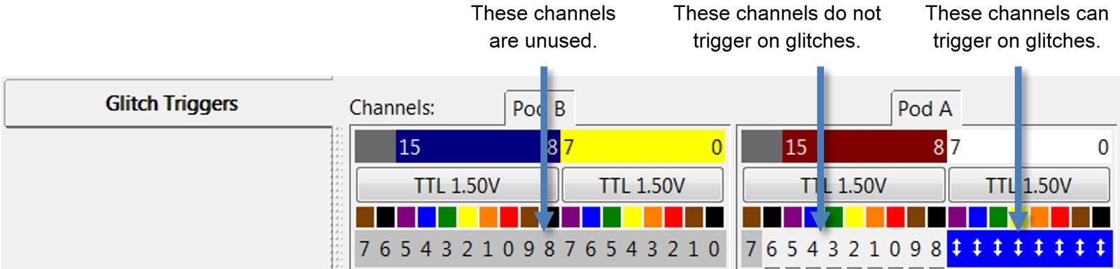
Each channel can be configured to ignore glitches or trigger when a glitch occurs...
|
| |
|
| |
|
All connected channels are stored in each trace sample. Channels with disabled glitch triggers are still stored in the sample. The glitch triggers only affect which channels can cause a trigger event.
|
| |
|
Channels which are not used in at least one channel group are assumed to be unconnected. These unconnected channels are ignored at run-time, cannot trigger the logic analyzer, and cannot detect glitches. This avoids unwanted noise or triggers caused by unconnected channels.
|
| |
|
When any channel detects a glitch event, the logic analyzer triggers and stops running.
|
| |
|
The Custom TriggerForm levels are also used to define the Glitch triggers. The Custom TriggerForm topic describes how glitch triggers are used in the TriggerForm levels.
|
| |
|
Copyright and trademark information
|

|