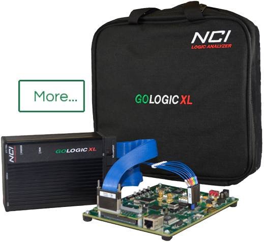
GoLogic Logic Analyzer by NCI
Digital Test and Measurement Tools
Transitional Timing mode at 1 GHz captures fast data-bursts separated by very long periods of bus inactivity. This is an ideal sample mode for modern serial bus decoding. State Analysis features support single data-rate SDR clocks up to 300 MHz and double data-rate DDR rates up to 250 MHz (effectively 500 MHz SDR). The GoLogicXL software provides an intuitive interface and offers many useful features no other test and measurement tools can match.
NCI is pleased to provide our customers with expert logic analyzer support before and after the sale. You can rely on us for high-quality products and exceptional service. Contact NCI our team with any questions you have regarding our products or how each one can help you. We value every customer.
Fast Sample Rates
The GoLogic has the speed to find the most difficult circuit debug issues. Sample rates from 10 KHz to 4 GHz can capture any digital signal.
Advanced Triggers
TriggerForms™ make the trigger setup easy. Value, Edge, and Range triggers let you detect any event. Timer and counters qualify each trigger event. Use up to 16 trigger levels to create a complex trigger series.
Deep Memory
1 billion samples captures a bigger picture. View errors and their after-effects with extremely large sample depths.
Transitional Sampling
Our Transitional Sampling mode stores data only when the captured signals change. The result is an extremely efficient capture mode perfect for extremely fast data bursts followed by long periods of inactivity.
Logic Analyzer Probe Options
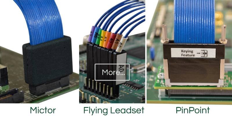
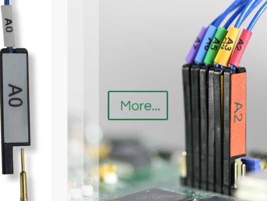
The GoLogicXL offers General-Purpose Leadsets, Mictor Probes, and PinPoint Probes to meet most testing needs. Both Mictor and PinPoint probe types are industry-standards used on many PCB designs. The PinPoint probe (also called “soft touch” or “connectorless” probes) is the best solution to capture high-speed signals with low-capacitance loading.
Differential and Single-ended Inputs
All NCI logic analyzer probe types support both single-ended and differential signals. Switching modes is just a software option.
Design Quality
All NCI logic analyzer probes…
- Use coaxial shielding for each leadset wire.
- Provide a ground for each channel to reject noise and avoid crosstalk.
- Use a passive circuit inside each lead-tip to preserve signal quality.
- Present low loads: 50 Kohm, 4.5 pF picofarad.
- Support 300 mV voltage swings.
GoLogic logic analyzer probes are 100% compatible with PCB connections used with other logic analyzer manufacturers. However, NCI probes can only be used with the GoLogicXL logic analyzer and cannot be used with other logic analyzer makers.
Mixed Signal Analysis
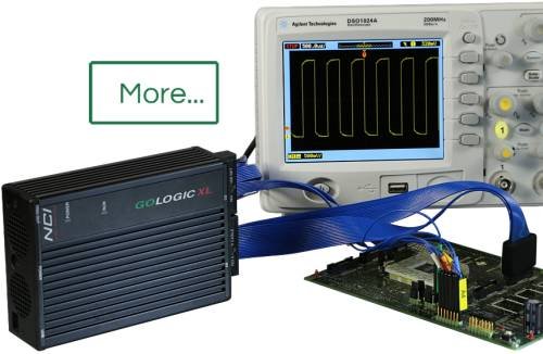
Connect our trigger-out BNC cable to your DSO and the GoLogicXL triggers your scope too. With each trace capture, ScopeLink™ downloads and time-aligns the analog DSO signals with the logic analyzer timing diagrams. View the raw analog signals from you DSO time-aligned with the timing diagrams inside the WaveForm view.
External Clock Speed
Our State Analysis mode supports 300 MHz SDR and 250 MHz DDR (500 MHz SDR effective) external clock speeds.
Serial Bus Analysis
The GoLogicXL logic analyzer supports the most common bus types used for embedded and automotive engineering...
- 1-Wire
- CAN / CAN-FD
- CLK + Data (custom bit-stream)
- DMX512
- I2C / MIPI I3C (SenseWire)
- I2S audio
- JTAG
- LIN
- MDIO / SMI
- ONFI-SDR
- PWM Encoder
- Quad SPI / SPI-MIO (SPI Multi-IO)
- SDIO / MMC / eMMC (Secure Digital)
- SENT (sensor data)
- SPI (Microwire, µ-wire, Microsecond Bus)
- UART (RS-232, RS-422, etc.)
Serial Bus Decode and Trigger
The GoLogicXL-36 Logic Analyzer includes Serial Bus Trigger and Decode features...
- Capture extremely long periods of low-level serial bus behavior.
- Capture up to 32 serial buses together, even different bus types.
- Trigger on complex serial bus packets and data values. Dedicated trigger hardware detects up to 128 "events" such as clock edges or baud bits. Complex packets with header values and data bytes can trigger the logic analyzer.
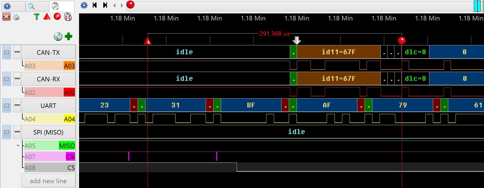
- The WaveForm view displays the decoded bus values time-aligned with the raw signals.
- Export the serial bus values to text or CSV files for outside software analysis using Excel or Mathcad.
Glitch Trigger and Capture
Glitch Capture mode allows the sampling rate to be slowed down yet alerts you when unusually small pulses occur on your digital signals. Glitches occur when the input signal passes through the threshold voltage two or more time between sample points. Since a glitch occurs between two sample points, the logic analyser must use specialized hardware to detect them. The GoLogicXL can trigger when a glitch occurs, plus mark all locations in a trace capture where they occur.
Software Trace Analysis
Our Trace Analysis Tools can remove noise and glitches automatically after each trace capture. We can also automatically compare all the samples in each trace capture to the correct values you define. All compare errors are counted so you know how many occur in each trace capture. The analysis tools can bookmark each error for later review.
Custom Logic Analyzer Software
NCI offers three ways to create custom logic analyzer software…
Software Developer’s Kit (SDK)
The SDK allows you to write a custom program that controls the GoLogicXL logic analyser device. Your program sends commands to capture and download trace data for dedicated analysis. The SDK is the perfect way to develop a custom production testing program or embed the GoLogicXL inside another product.
Plugin Developer’s Kit (PDK)
The PDK allows you to write a custom plugin for the GoLogicXL user interface. Create a custom text view that automatically processes each trace capture. The results are displayed in a view pane inside the GoLogicXL software. Scroll your custom window along with our WaveForm, Numeric, and Serial Bus Display text views.
Analysis Development Kit (ADK)
The ADK allows you to create custom Analysis Tools for the GoLogic7 logic analyzer software. Your analysis plugin executes and displays results after each trace capture. Each plugin can display a message summary, save a custom text file, or bookmark specific samples in the trace capture. Analysis plugins can also create modified trace data for display in the WaveForm and Numeric views.

