Logic Analyzer Features
The GoLogicXL Logic Analyzer provides advanced abilities few other tools can match. NCI offers industry-standard Logic Analyzer features, faster sample rates, deeper memory, and advanced triggers. You can depend on our accurate, sensitive hardware and productive software tools. Discover how our logic analysers can accelerate your digital hardware and firmware development.
Logic Analyzer Probe Options
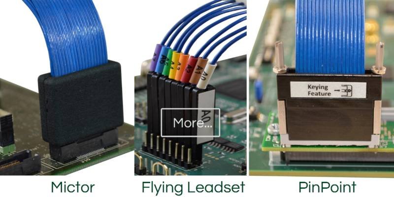
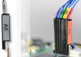
The GoLogicXL offers General-Purpose Leadsets, Mictor Probes, and PinPoint Probes to meet most testing needs. Both Mictor and PinPoint probe types are industry-standards used on many PCB designs. The PinPoint probe (also called “soft touch” or “connectorless” probes) is the best solution to capture high-speed signals with low-capacitance loading.
GoLogic logic analyzer probes are 100% compatible with PCB connections used with other logic analyzer manufacturers. However, NCI probes can only be used with the GoLogicXL logic analyzer and cannot be used with other logic analyzer makers.
The GoLogic7 software offers a dedicated editor for each probe type: Pods, Spreadsheet, Mictor, and PinPoint.
Accurate Sensitive Probes
All GoLogicXL probes maintain signal integrity by coaxially shielding each input wire. Each channel tip also includes passive circuitry to minimize loading. Logic analyzer probes that lack shielding or circuitry can create loading and crosstalk problems. Logic Analyzer Probes that distort the signals cause problems.
Advanced Triggers
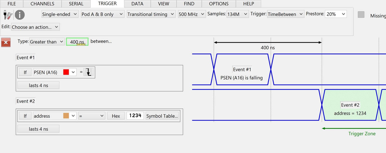
Enormous sample depths cannot substitute for logic analyzer triggering. The GoLogicXL TriggerForms provides value, edge, and range triggers plus timers and counters. With these logic analyzer trigger tools, any event in your digital signals can be detected. The Simple, Series, and TimeBetween TriggerForms™ simplify the setup when the full trigger capabilities are not needed. For the most advanced trigger needs, the Custom TriggerForm exposes all GoLogicXL trigger features.

GHz Sample Rates
Logic analyzers must have the speed to recreate your signals accurately. The GoLogicXL is one of very few logic analysers offering up to 4 GHz sampling rates.
Deep Memory
Sometimes there is no substitute for a large trace capture where the cause and effect of a problem are separated by a long time period. With up to 2 GB of installed high-speed memory, the GoLogicXL can capture up to 1 billion samples per channel across 9 channels.
USB “streaming” logic analyzers offer slower sampling rates across few channels. The Logic Analyzer Streaming topic discusses why NCI logic analyzers do not stream data directly to disk.
300 MHz State Analysis
In State Analysis mode, an external clock signal from your device defines when the logic analyzer latches the input signals. The GoLogicXL can be configured so that trace is captured on the input clock signal’s rising edge, falling edge, or both edges (double data rate, DDR). Moreover, the GoLogicXL provides two State Analysis modes for maximum versatility. The first mode allows any logic analyzer channel to be defined as a clock input or qualifier. Up to 8 channels can be used to define when the input signals are latched. However, this flexibility limits the maximum clock speed allowed. For fast clock signals, our logic analysers offers a dedicated clock channel which is connected to your device’s clock signal. Using a Phase Link Loop, this high-speed clock channel can sync with clock signals up to SDR 300 MHz single data rate or DDR 250 MHz double data rate (500 MHz effective).
Differential and Single-Ended Probes
The GoLogicXL captures both single-ended and differential inputs using any of our probing options: flying leadset, Mictor, or PinPoint. Very few logic analyzers can capture differential input signals.
The GoLogicXL supports a 300 mV minimum voltage swing in single-ended input mode, and a 150 mV minimum in differential input mode.
1 GHz Transitional Sampling
Few logic analyzers provide Transitional Timing mode. This extremely powerful GoLogicXL feature provides high-resolution trace captures that also span very long periods of time.
Glitch Trigger and Capture
Our Glitch Capture sampling mode allows the sampling rate to be slowed down yet alerts you when unusually small pulses occur on your digital signals. Glitches occur when the input signal passes through the threshold voltage two or more time between sample points. Since a glitch occurs between sample points, the logic analyser must use specialized hardware to detect them. The GoLogicXL can trigger when a glitch occurs, plus mark all locations in a trace capture where they occur.
SuperView Trace Overlay
The SuperView™ overlay is a window of high-resolution trace data simultaneously captured on all channels centered around the trigger event. Toggle the SuperView overlay in the WaveForm window for a snapshot of what really happened near that error you found.
Serial Bus Analysis
The GoLogicXL logic analyzer supports the most common bus types used for embedded and automotive engineering...
- 1-Wire
- CAN / CAN-FD
- CLK + Data (custom bit-stream)
- DMX512
- I2C / MIPI I3C (SenseWire)
- I2S audio
- JTAG
- LIN
- MDIO / SMI
- ONFI-SDR
- PWM Encoder
- Quad SPI / SPI-MIO (SPI Multi-IO)
- SDIO / MMC / eMMC (Secure Digital)
- SENT (sensor data)
- SPI (Microwire, µ-wire, Microsecond Bus)
- UART (RS-232, RS-422, etc.)
Serial Bus Decode and Trigger
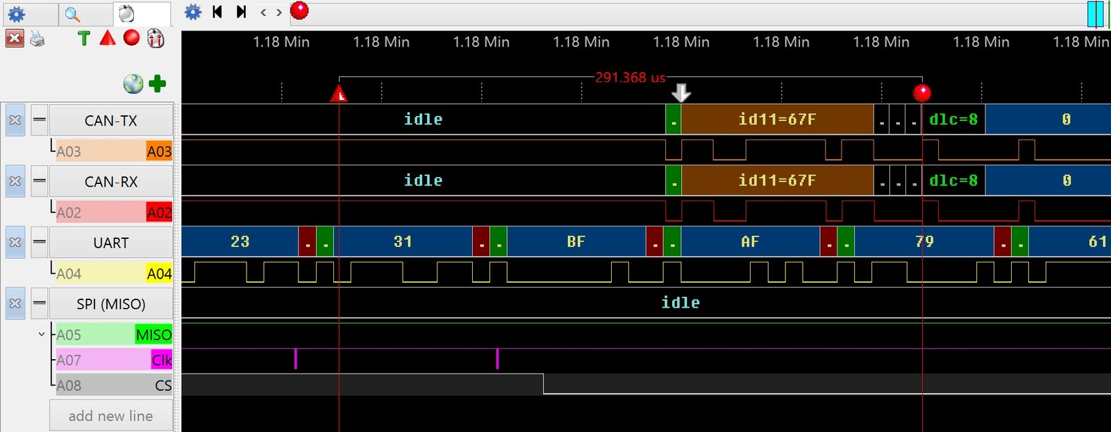
The GoLogicXL-36 Logic Analyzer includes Serial Bus Trigger and Decode features...
- Capture extremely long periods of low-level serial bus behavior.
- Capture up to 32 serial buses together, even different bus types.
- Trigger on complex serial bus packets and data values. Dedicated trigger hardware detects up to 128 "events" such as clock edges or baud bits. Complex packets with header values and data bytes can trigger the logic analyzer.
- The WaveForm view displays the decoded bus values time-aligned with the raw signals.
- Export the serial bus values to text or CSV files for outside software analysis using Excel or Mathcad.


