|
<< Contents
<< Workbar
<< WorkBar Tabs
<< CHANNELS
|
| |
|
|
| |
|
Click the "A/D Conversion" button to edit the formula used to convert analog values.
|
| |
 |
| |
|
Channel groups must contain 2 or more channels to use the A/D Conversion feature.
|
| |
|
Channels connected to a sensor's digital output (voltage, current, temperature, etc.) can be displayed as analog values.
|
| |
|
Sensor which output their values via serial bus (SPI, I2C, UART, etc.) can be displayed as analog values using the A/D Conversion feature in the Serial Tab.
|
| |
|
| |
|
|
| |
|
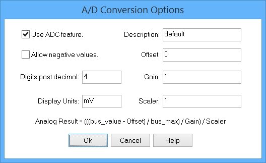
Check this option to enable the formula for the channel data.
|
| |
|
|
| |
|
Check this option to allow negative results.
|
| |
|
|
| |
|
Enter the number of digits displayed past the decimal point.
|
| |
|
Display Units:
|
| |
|
Enter the text to display next to each analog result value.
|
| |
|
|
| |
|
The offset and gain values depend on the sensor. The manufacturer's documentation for the sensor provides the offset and gain value.
|
| |
|
The scaler value is used to adjust the result for the units you want to display.
|
| |
|
For example, if the scaler is 1 and the analog result is 0.00145 volts, then entering a scaler of "0.001" adjusts the result to 1.45 mV.
|
| |
|
Likewise, using a scaler value of 100 adjusts 1450 mV to 1.45 volts.
|
| |
|
The formula used to convert the digital bus values to analog result is...
|
| |
|
Result = (((bus_value - Offset) / bus_max) / Gain) / Scaler
|
| |
|
The "bus_max" value is defined by the number of channels in the group.
|
| |
|
For example, a 16-bit group's maximum value is 65,535.
|
| |
|
Copyright and trademark information
|

|