 |
Delete Bus Button |
| Deletes the serial bus definition. | |
 |
Expand / Collapse Button |
| Expand / collapse the serial bus definition area. This is very useful when many serial buses exist in a project. | |

|
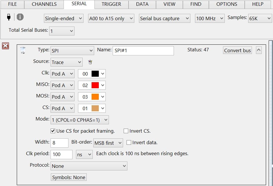
Type List |
| Select the serial bus type. | |
 |
Name Edit Box |
| Enter a meaningful name for the serial bus. | |
 |
Convert Bus Button |
| Force the raw signals to be decoded into formatted bus values. Use this button after changing the baud, channels, or other bus parameters. Otherwise, the serial decoding is automatic with each new trace capture. | |
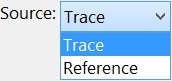 |
Decode Data List |
| Select the source data to decode: Trace or Reference. This option defines which data is used to decode the serial bus data. | |
 |
Bus Colors |
| Displays the Serial Bus Colors dialog box. |
