|
<< Contents
<< Workbar
<< WorkBar Tabs
<< CHANNELS
|
| |
|
|
| |
|
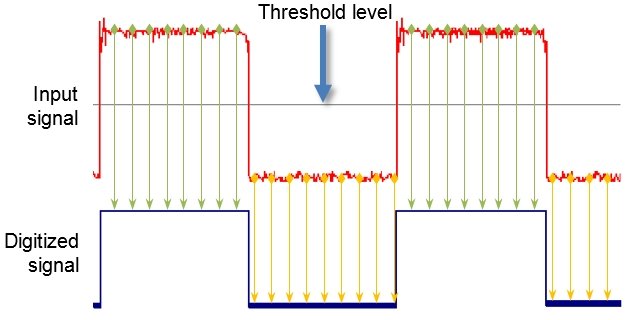
The threshold level determines how the logic analyzer interprets the input signals.
|
| |
|
Input voltages "below" the threshold are converted to '0' (logic-low).
|
| |
|
Input voltages "above" the threshold are converted to '1' (logic-high).
|
| |
|
In the example below, the green sample-points are above the threshold level and are interpreted as a logic-high. The yellow sample-points are below the threshold level and are interpreted as a logic-low.
|
| |
|
| |
|
|
| |
|
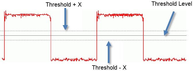
A small indeterminate voltage range exists around the threshold voltage level...
|
| |
|
| |
|
The input signal value is unpredictable in this small region near the threshold voltage. This region is defined by the precision limits of the logic analyzer's voltage sensors.
|
| |
|
Always define the threshold levels so the input signals spend the least possible time in this indeterminate voltage range.
|
| |
|
For example, avoid setting the threshold to 0.1 V if the signals logic-low voltage is 0 V. Set the threshold well above this 0 V logic-low "noise floor".
|
| |
|
The Appendices define each model's minimum voltage swing.
|
| |
|
|
| |
|
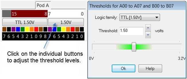
Click the threshold buttons in the Channels view to set the threshold levels...
|
| |
|
| |
|
Logic Family
|
| |
|
Select a logic family to set the threshold level to a "typical" threshold voltage for that logic type. This default threshold level is normally mid-way between the logic-low and logic-high voltages.
|
| |
|
The logic family does not limit the logic analyzer's threshold boundaries.
|
| |
|
Regardless of the selected logic family, the threshold level can be adjusted to any voltage the logic analyzer supports.
|
| |
|
The Appendices define each model's threshold voltage limits.
|
| |
|
Edit Box
|
| |
|
Enter a threshold level voltage.
|
| |
|
Up / Down Buttons
|
| |
|
Make minimum step-adjustments to the threshold voltage level.
|
| |
|
Scroll Bar
|
| |
|
Make quick threshold level changes with the scroll bar slider.
|
| |
|
The selected logic family affects the appearance of the scroll bar.
|
| |
|
The green center region suggests the best threshold range for the logic family.
|
| |
|
The regions on either side of the green area are outside the typical threshold voltage for the active logic family.
|
| |
|
However, the active logic family does not affect the scale of the scroll bar. The threshold level can be adjusted to any voltage the logic analyzer supports.
|
| |
|
The scroll bar's end tick-marks display the minimum (left) and maximum (right) threshold voltage limits.
|
| |
|
The Appendices define each model's threshold voltage limits.
|
| |
|
Copyright and trademark information
|

|