|
<< Contents
<< Workbar
<< WorkBar Tabs
<< SERIAL
|
| |
|
|
| |
|
| |
|
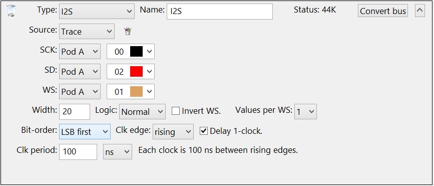
Inter-Integrated Circuit Sound (I2S)
|
| |
|
|
| |
|
Select the channels connected to the raw bus signals.
|
| |
|
Warning: DO NOT create duplicate Channel Groups for the serial bus signals! The GoLogic7 software automatically creates a hidden channel group for each signal in the serial bus. If needed, these hidden channel groups can be used to trigger or display the raw signals in the data views.
|
| |
|
When project files are opened, the GoLogic7 software automatically deletes channel groups which duplicate the serial bus channels. This avoid potential conflicts between the channel groups and the serial bus definitions.
|
| |
|
|
| |
|
Enter the width of each data value.
|
| |
|
|
| |
|
Select the SD signal logic type: Normal or Inverted.
|
| |
| |
Logic: Normal
|
| |
The SD signal is logic-high for 1 bit-values.
|
| |
|
| |
Logic: Inverted
|
| |
The SD signal is logic-low for 1 bit-values.
|
|
| |
|
|
| |
|
When checked, the WS signal logic is inverted.
|
| |
|
|
| |
|
Select the data values transmitted during each active WS signal.
|
| |
|
|
| |
|
Select the data value bit-order: LSB or MSB first.
|
| |
|
|
| |
|
Select the clock signal edge to latch the data bits: rising, falling, or both.
|
| |
|
|
| |
|
When checked, the first clock edge of each data value is ignored.
|
| |
|
|
| |
|
Enter the elapsed time from rising edge to rising edge.
|
| |
|
Copyright and trademark information
|

|