A = least significant bit
Increment count by 1 when BA changes from 0 to 2, or 2 to 3, or 3 to 1, or 1 to 0
Decrement count by 1 when BA changes from 0 to 1, or 1 to 3, or 3 to 2, or 2 to 0

| << Contents << Workbar << WorkBar Tabs << SERIAL |
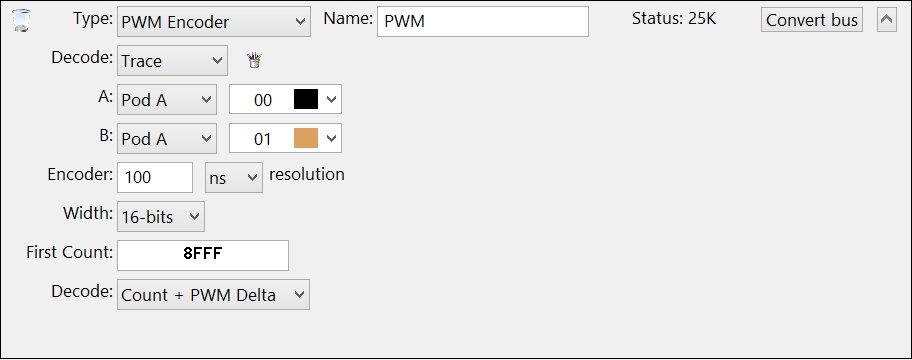
| Bus Type: PWM Encoder |
|
|
| Pulse Width Modulation (PWM) |
| A / B |
| Select the channels connected to the raw A and B signals. If the B signal is not availalbe, choose the same channel as A. |
| Warning: DO NOT create duplicate Channel Groups for the serial bus signals! The GoLogic7 software automatically creates a hidden channel group for each signal in the serial bus. If needed, these hidden channel groups can be used to trigger or display the raw signals in the data views. |
| When project files are opened, the GoLogic7 software automatically deletes channel groups which duplicate the serial bus channels. This avoid potential conflicts between the channel groups and the serial bus definitions. |
| Encoder resolution |
| Enter the smallest time-delta for each pulse width. This value can be equal to or less than the encoder sampling rate. The encoder resolution value is used to calculate the amount of change between each pulse width. |
| Width |
| Select the decoded value width: 8, 16, 32, or 64 bits. |
| First Count |
| Enter a hexadecimal value that is copied into the decoded data at index 0. All following values in the decoded data are based off this first count value. |
| Decode |
| Select how you want the PWM / Quadrature to be decoded. |
| Decode: Count + PWM Delta |
| All values after the "First Count" are set based on the changing pulse widths. Each pulse width change defines a value which is then added or subtracted from the prior count value. As the pulses become wider, the encoder is assumed to be slowing down, so the change is subtracted from the prior counter value. As the pulses become more narrow, the encoder is assumed to be speeding up, so the change is added to the prior counter value. The quadrature code is not used to determine when to add or subtract changes. This allows the decode to work with a single PWM signal if needed. |
| Decode: PWM Delta only |
| All values after the "First Count" are the PWM Delta value without adding to the count. 0 indicates no change between pulses. A "value+" indicates the pulse was more narrow (faster) than the prior pulse. A "value-" indicates the pulse was wider (slower) than the prior pulse. |
| Decode: Count + Quadrature |
| All values after the "First Count" are incremented or decremented by 1 based on the quadrature code direction. The quadrature code direction is derived from the A and B signals as follows... |
|
B = most significant bit A = least significant bit Increment count by 1 when BA changes from 0 to 2, or 2 to 3, or 3 to 1, or 1 to 0 Decrement count by 1 when BA changes from 0 to 1, or 1 to 3, or 3 to 2, or 2 to 0 |
| Copyright and trademark information |
|
|