|
<< Contents
<< Workbar
<< WorkBar Tabs
<< SERIAL
|
| |
|
|
| |
|
SPI bus operation can vary between implementations, and you must know exactly how your bus operates.
|
| |
|
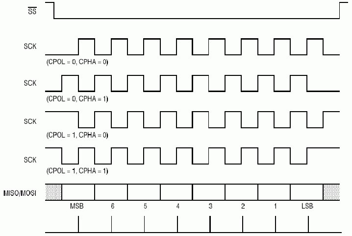
SPI bus offers four operating modes. The mode defines whether the data bits are latched on the clock's rising or falling edge. The mode also defines the clock's state (high or low) when the bus is inactive.
|
| |
|
CPHAS is the clock "phase" value. CPOL is the clock "polarity" value. These values define how the serial SPI bits are latched. The four SPI bus modes are defined as follows...
|
| |
| Mode
|
CPOL
|
CPHAS
|
Description
|
| 0
|
0
|
0
|
Clock inactive low, data latched on rising edge
|
| |
|
|
|
| 1
|
0
|
1
|
Clock inactive low, data latched on falling edge
|
| |
|
|
|
| 2
|
1
|
0
|
Clock inactive high, data latched on falling edge
|
| |
|
|
|
| 3
|
1
|
1
|
Clock inactive high, data latched on rising edge
|
|
| |
|
The following timing diagram illustrates the SPI bus modes...
|
| |
|
| |
|
SPI has no official IEEE standards and each implementation can differ. Specifically, the CS/SS* signal can be used as either a "frame" or a "chip select" mechanism.
|
| |
|
Copyright and trademark information
|

|