|
<< Contents
<< Workbar
<< WorkBar Tabs
|
| |
|
|
| |
|
The CLOCKS tab displays the clock toolbar to define the State Analysis behavior.
|
| |

|
| |
|
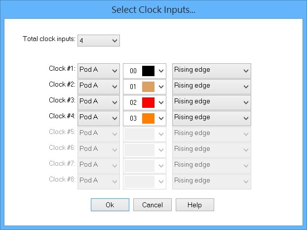
Select the channel inputs that drive the logic analyzer using State Analysis mode.
|
| |
|
|
| |
|
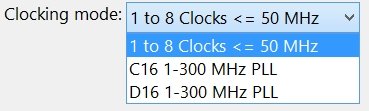
State analysis offer two operating modes...
|
| |
 |
| |
|
|
| |
 |
| |
|
The "1 to 8 Clocks" mode supports slower clock rates but is more flexible.
|
| |
Click the  ToolBar button to select the clock inputs... ToolBar button to select the clock inputs...
|
| |
 |
| |
|
* Up to 8 clock signals from the test circuit can define when the logic analyzer stores each trace sample to memory.
|
| |
|
* The source clocks can be captured in the trace data.
|
| |
|
* The active channels determine the maximum input clock frequency.
|
| |
|
* The input clock frequency cannot exceed 50 MHz when 72 channels are active.
|
| |
|
* The input clock frequency cannot exceed 100 MHz when 36 channels are active.
|
| |
|
* The input clock frequency cannot exceed 200 MHz when 16 channels are active.
|
| |
|
* The signals can be latched on the rising edge, falling edge, or both clock edges. A logic-low or logic-high clock can also be combined with the edges.
|
| |
|
* At least one edge must be used in the clock equation.
|
| |
|
* Rising and falling edges are grouped together.
|
| |
|
* Logic-high and logic-low clocks are grouped together.
|
| |
|
* Edges are combined using an OR operator.
|
| |
|
* Logic-high and logic-low clocks are combined using an OR operator.
|
| |
|
* Edges and logic groups are combined last with an AND operator.
|
| |
|
* The final clock equation is painted below the last clock signal.
|
| |
|
* The clock signals can idle and restart without losing sync.
|
| |
|
* A timestamp records each trace sample's elased time.
|
| |
|
* The first clock signal has a frequency counter feature. The detected frequency is displayed when possible. The displayed value uses one edge (single data rate) for the frequency.
|
| |
|
|
| |
 |
| |
|
This mode supports faster external clocks rates, but is less flexible than the "1 to 8 Clocks" mode.
|
| |
|
Use PLL mode when the source clock is too fast for the "1 to 8 Clocks" option.
|
| |
|
* A high-speed Phase Link Loop (PLL) synchronizes the logic analyzer with your source clock signal.
|
| |
|
* The PLL cannot sync with a clock signal slower than 1 MHz.
|
| |
|
* The PLL cannot sync with non-periodic or asymmetric input clock signals.
|
| |
|
* The input clock signal cannot idle.
|
| |
|
* When 72 channels are active, the clock signal must be connected to channel C16 or D16.
|
| |
|
* When 36 channels are active, the clock signal must be connected to channel A16 or B16.
|
| |
|
* The clock signal can be latched on the rising edge or falling edge when 36 or 72 channels are active.
|
| |
|
* The clock signal can be latched on both edges only when 36-channels are active.
|
| |
|
* Source signal quality determines the maximum allowable frequency.
|
| |
|
* No timestamps are recorded. All samples have the same elapsed time.
|
| |
|
* A frequency counter detects the clock signal's frequency. This frequency value is used to display the captured trace data.
|
| |
|
* The clock signal is not captured in the trace data. By definition, the clock signal "drives" the logic analyzer circuits and can't be captured. The clock signal is always logic-high when latching on rising edges and is always logic-low when latching on falling edges.
|
| |
|
The Appendices define each model's external clock rate limits.
|
| |
|
Copyright and trademark information
|

|