The NCI logic analyzer software can control newer-model Tektronix® or Keysight® digital storage oscilloscope (DSO) configured for single-shot mode.
ScopeLink does not define the scope's voltage scale or sampling rate. Configure the scope via its front panel to display the signals on-screen before enabling ScopeLink. Some scope models lock out their front panel after VISA connects to the scope.
When the ScopeLink™ Wizard starts , an error message is displayed if VISA cannot connect to at least one device. Simply exit the wizard, correct the issue, then try again.
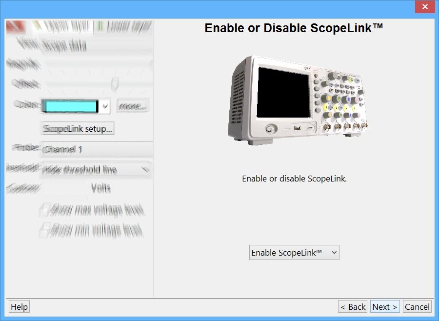
Step 1: Enable or Disable
ScopeLink can be disabled in this step, or by deleting all WaveForm lines that display scope data.
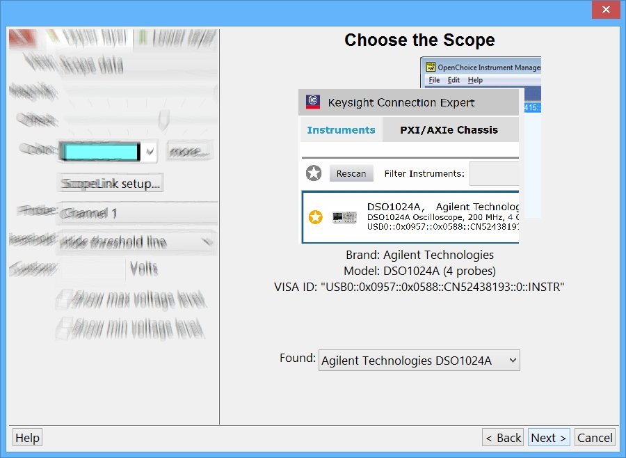
Step 2: Choose the Scope
Select the scope to use with ScopeLink. All scopes VISA detects are available in the list box.
ScopeLink controls only one external scope.
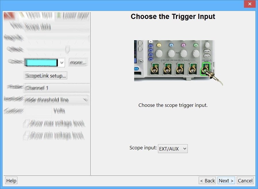
Step 3: Choose the Trigger Input
Choose the scope's trigger input that will be connected to the ScopeLink cable.
Choose the EXT/AUX input if the scope offers that option.
Otherwise, choose one of the probe inputs as the trigger input.
The logic analyzer must trigger the scope for ScopeLink to funtion correctly.
The logic analyzer trigger-out signal physically ties the scope capture to the logic analyzer trace capture.
This method means that an unavoidable time-skew exists between the scope data and logic analyzer data.
This time-skew is due to unavoidalbe physical delays in the logic analyzer trigger-out circuits, the ScopeLink cable, and the scope's trigger input circuits.
However, any time-skew is automatically removed by the software after each download (when ScopeLink is configured correctly).
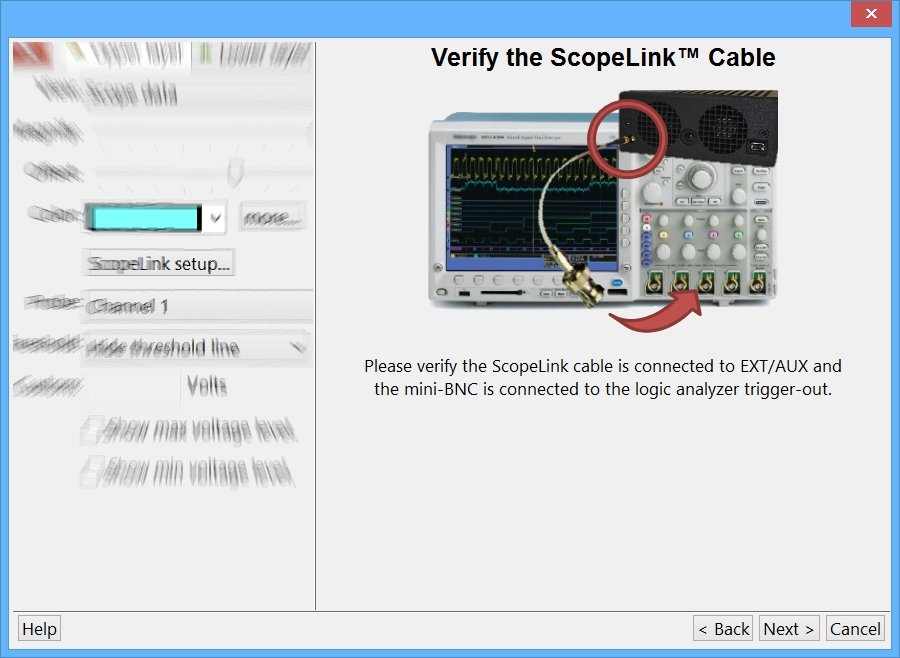
Step 4: Verify the ScopeLink™ Cable
Connect the ScopeLink cable micro-BNC end to the logic analyzer.
Connect the ScopeLink cable standard-BNC end to the scope trigger input selected in the prior step.
If you forget the ScopeLink cable, the scope won't trigger and no scope data is downloaded.
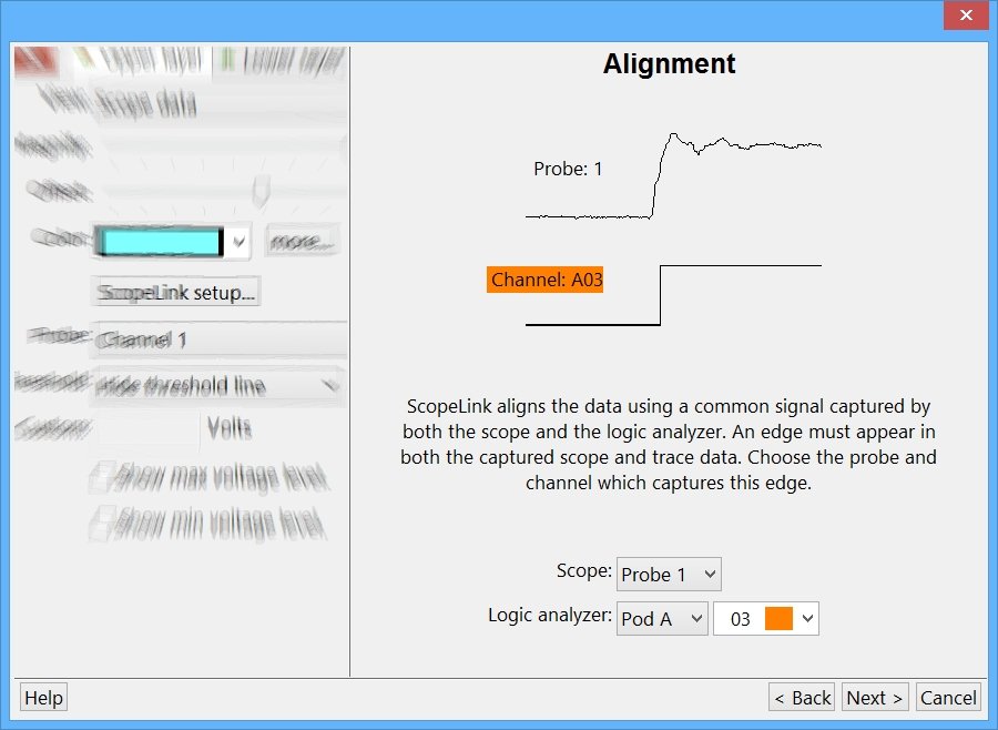
Step 5: Choose the Alignment Probe and Channel
Choose a scope probe and a logic analyzer channel that will capture the same shared signal.
To time-align the scope and logic analyzer trace data, this shared signal must be captured by both the scope and the logic analyzer.
At least one edge must exist on the shared signal when it is captured.
If the captured signal is has no edges, the scope and trace data cannot be time-aligned.
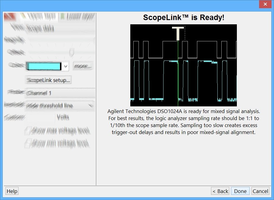
Step 6: Finish
Click the Done button. The scope will automatically start running, trigger, capture, and be downloaded with each logic analyzer trace capture.