|
<< Contents
<< Workbar
<< WorkBar Tabs
<< SERIAL
|
| |
|
|
| |
|
| |
|
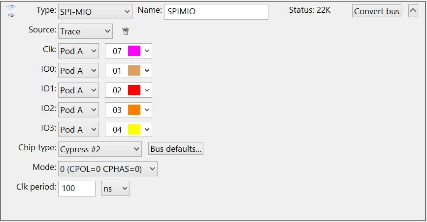
Quad Serial Peripheral Interface (Quad SPI)
Also called "SPI Multi Input/Output" or "SPI-MIO"
|
| |
|
|
| |
|
Select the channels connected to the raw bus signals.
|
| |
|
Warning: DO NOT create duplicate Channel Groups for the serial bus signals! The GoLogic7 software automatically creates a hidden channel group for each signal in the serial bus. If needed, these hidden channel groups can be used to trigger or display the raw signals in the data views.
|
| |
|
When project files are opened, the GoLogic7 software automatically deletes channel groups which duplicate the serial bus channels. This avoid potential conflicts between the channel groups and the serial bus definitions.
|
| |
|
|
| |
|
Select the manufacturer to define the active command table.
|
| |
|
If no manufacturer matches your chip, then select the "Custom..." option and create a custom command table for your chip.
|
| |
|
The "spimio_cmds.txt" file is saved to your "My Documents" folder. Edit this file to match your chip's command table. This file is loaded when the GoLogic7 software starts provided the "Custom..." chip type is selected.
|
| |
|
|
| |
|
Enter the default bus behaviors...
|
| |
| |
Data clock edge: by command, force rising, force falling.
|
| |
|
| |
Data speed: by command, force dual, force quad.
|
| |
|
| |
Address bits: Enter 2 to 32 (24 is default)
|
| |
|
| |
Dummy bits: 2 to 32 (8 is default)
|
| |
|
| |
Mode bits: 2 to 32 (8 is default)
|
|
| |
|
|
| |
|
Select the SPI Mode.
|
| |
|
|
| |
|
Enter the elapsed time from rising edge to rising edge.
|
| |
|
Copyright and trademark information
|

|