|
<< Contents
<< Workbar
<< WorkBar Tabs
<< CHANNELS
|
| |
|
|
| |
 |
| |
|
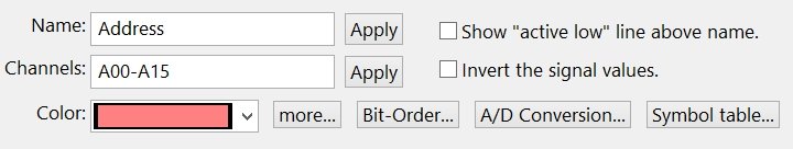
These edit controls are common to all Display Types in the Channels view.
|
| |
|
|
| |
 |
| |
|
Enter a meaningful name indicating the group's purpose with this control. For example, channels connected to the address signals from a microprocessor might be given the name "address bus".
|
| |
|
Click the "Apply" button when finished entering the group name. Otherwise, the changes won't appear until the Channels Tab is closed.
|
| |
|
Each group name can be up to 127 characters long. Using names less than 30 characters is recommended because long names may be truncated if they do not fit in an area.
|
| |
|
|
| |
 |
| |
|
The channels edit box can also be used to define the channels in each group.
|
| |
|
Enter a Channel String to define the channels in the group.
|
| |
|
Click the "Apply" button when finished entering the channel definition string. Otherwise, the changes won't appear until the Channels Tab is closed.
|
| |
|
|
| |
 |
| |
|
When checked, this option displays a decorator line above the group name. This is a common naming convention to indicate signals which are active when the value is logic-zero.
|
| |
|
|
| |
 |
| |
|
When checked, this option inverts the displayed signal values. This only affects how the signals are displayed in the software. A logic-one measured at the source remains a "1" in the captured trace data, but a "0" is displayed on screen.
|
| |
|
|
| |
 |
| |
|
Choose a unique color for each channel group. The "More..." button allows a custom color to be assigned to any group.
|
| |
|
|
| |
 |
| |
|
Click the Bit-Order... button to edit the channel order inside the group.
|
| |
|
|
| |
 |
| |
|
Click the A/D Conversion button to edit the formula used to convert analog values.
|
| |
|
|
| |
 |
| |
|
Click the Symbol Table button to select a symbol table for the channel group values.
|
| |
|
Copyright and trademark information
|

|