|
<< Contents
<< Workbar
<< WorkBar Tabs
<< SERIAL
|
| |
|
|
| |
|
| |
|
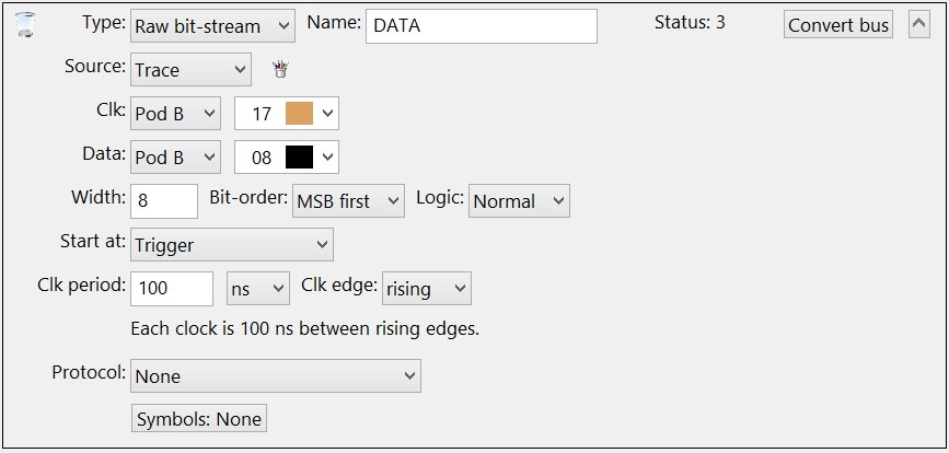
Decode a simple clock and data signal into parallel values.
|
| |
|
|
| |
|
Select the channels connected to the raw bus signals.
|
| |
|
Warning: DO NOT create duplicate Channel Groups for the serial bus signals! The GoLogic7 software automatically creates a hidden channel group for each signal in the serial bus. If needed, these hidden channel groups can be used to trigger or display the raw signals in the data views.
|
| |
|
When project files are opened, the GoLogic7 software automatically deletes channel groups which duplicate the serial bus channels. This avoid potential conflicts between the channel groups and the serial bus definitions.
|
| |
|
|
| |
|
Enter the data value width: 2 to 64 bits.
|
| |
|
|
| |
|
Select the bit-order: LSB or MSB arrives first.
|
| |
|
|
| |
|
Select the data signal's logic type: Normal or Inverted.
|
| |
|
Logic: Normal
|
| |
|
The data signal is logic-high for 1 bit-values.
|
| |
|
Logic: Inverted
|
| |
|
The data signal is logic-low for 1 bit-values.
|
| |
|
|
| |
|
Select the location in the trace capture to begin decoding: first sample, trigger sample, find a break period, red triangle marker, or red circle marker.
|
| |
|
|
| |
|
Enter the elapsed time from rising edge to rising edge.
|
| |
|
|
| |
|
Select the clock signal edge to latch the data bits: rising, falling, or both.
|
| |
|
|
| |
|
The Raw Bit-stream is a generic bus with no protocol. The Protocol List allows a Custom Protocol to be applied to the bus data.
|
| |
|
|
| |
|
Click this button to use a Symbol Table with the data values.
|
| |
|
Copyright and trademark information
|

|