|
<< Contents
<< Workbar
<< WorkBar Tabs
<< SERIAL
|
| |
|
|
| |
|
Generic serial bus types allow the decoded data values to be interpreted as a user-defined protocol. Generic serial bus types include I2C, SPI, UART, and Clk+Data bitstream. Note: these bus types do not support varying width decoded values. All protocol fields have the same bit-width.
|
| |
|
Each user-defined protocol groups the decoded serial bus values into packets. Each packet's size can be fixed or vary. For the I2C bus type, the packet size is always framed by the 'Start' and 'Stop' tokens. For the SPI bus type, the packet size can be framed by the 'CS' signal if it is used. For UART, Clk+Data, and SPI without the CS signal, each packet's size can be set by a "count" field or a pre-selected value.
|
| |
|
|
| |
|
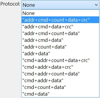
Select how the decoded data values will be interpreted...
|
| |
 |
| |
|
|
| |
|
* None: the decoded data values are displayed without a protocol. This is the default option for all bus types.
|
| |
|
* Addr+Cmd+Count+Data+CRC: the first value in each packet represents an address, the second value represents a command, the third value represents a packet length value, the forth through the next-to-last value are data, and the last value in each packet represents a CRC.
|
| |
|
The other formats follow the same rules.
|
| |
|
|
| |
The decoded field colors can be customized. Click the  button to customize the Serial Bus Colors. button to customize the Serial Bus Colors.
|
| |
| |
|
|
| |
|
The UART, Clk+Data, and SPI bus types offer a packet size option. This option defines how the packets are framed.
|
| |
|
The Packet Size option is not available for I2C because packets are always framed by the 'Start/Stop' token.
|
| |
|
* The "CS Frame" option is available for SPI when the CS signal is used.
|
| |
|
* The "Count Frame" option is available when the protocol includes the "count" element.
|
| |
|
* The "Any Number" option uses no packet framing. Any number of values appear in each packet.
|
| |
|
* The "Break" option looks for an inactive period between decoded values. An inactive period lasting at least 1.5 data values must occur to separate packets. Define the correct clock speed, clock period, or baud rate so the decoder can accurately recognize breaks between packets.
|
| |
|
The raw signals must be inactive for at least 1.5 data values to force a break period between packets. For example, if the bus uses 8-bit data values, a break is detected when the raw signals are inactive for at least a 12-bit time span.
|
| |
|
* Custom: select (or enter) a packet size value which divides the decoded values into uniform packets beginning at the trace data start.
|
| |
|
|
| |
|
Click the "Address Symbols", "Cmd Symbols", and "Data Symbols" buttons to select Symbol Tables for each protocol field.
|
| |
|
Copyright and trademark information
|

|