|
<< Contents
<< Workbar
<< WorkBar Tabs
<< TRIGGER
<< Serial Bus Trigger
|
| |
|
|
| |
|
The logic analyzer triggers when the packet matches the TriggerForm values.
|
| |
|
The CAN / CAN-FD TriggerForm does not allow the "anything" placeholder "x" digit to appear in any fields. Since stuff-bits are inserted into the bit-stream, any "x" digits creates an undefined stuff-bit count. Therefore, all trigger fields must contain determinate values.
|
| |
 |
| |
|
Trigger on stuff-bit errors.
|
| |
|
When checked, the logic analyzer triggers on incorrect stuff-bits inserted into the bit-stream.
|
| |
|
When unchecked, the logic analyzer ignores incorrect stuff-bits.
|
| |
|
DO NOT check this option unless all header, RTR, DLC, and data bytes are entered correctly.
|
| |
|
Type
|
| |
|
Select the header field size: "11 bit" or 11+18 bit".
|
| |
|
ID Qualifier
|
| |
|
Select the "=" or "!=" qualifier for the ID fields.
|
| |
|
ID11 Value
|
| |
|
Enter the 11-bit ID field.
|
| |
|
ID18 Value
|
| |
|
Enter the 11-bit ID field.
|
| |
|
ID Base
|
| |
|
Click the "Hex" or "Binary" button to choose the numeric base for the ID edit boxes. This option is cosmetic and has no affect on the trigger behavior.
|
| |
|
RTR
|
| |
|
Define the "Remote Transmission Request" (packet direction flag).
|
| |
|
DLC
|
| |
|
Select the Data Length Code field (packet byte count).
|
| |
|
The DLC selection determines now many data values appear in the packet.
|
| |
|
However, fewer data bytes may actually be active in the final trigger.
|
| |
|
The logic analyzer can trigger on up to 64 raw CAN / CAN-FD serial bits.
|
| |
|
This limit includes start-bit, header bits, data bits, and stuff-bits.
|
| |
|
The stuff bit count changes depending on the content of the header and data fields. Therefore, the total bits allows in the CAN trigger setup varies.
|
| |
|
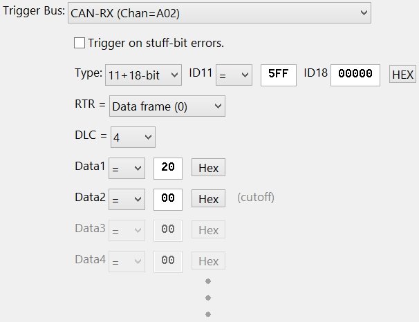
In the above screen capture example, only two data bytes are allowed in the trigger. The "cutoff" indicates the 64-bit limit is reached on the second data byte. The disabled 3rd and 4th data bytes are not included in the final trigger.
|
| |
|
These limits only affect the hardware trigger feature. Complete packets are always captured in the trace data and displayed in the WaveForm and Serial Bus Text views.
|
| |
|
The Appendices define each model's trigger limits.
|
| |
|
Data Qualifiers
|
| |
|
Select the "=" or "!=" qualifier for each data byte in the series.
|
| |
|
Data
|
| |
|
Enter each data value in the packet.
|
| |
|
Base
|
| |
|
Click the "Hex" or "Binary" button to choose the numeric base for the data edit boxes. This option is cosmetic and has no affect on the trigger behavior.
|
| |
|
Copyright and trademark information
|

|