|
<< Contents
<< Workbar
<< WorkBar Tabs
<< SERIAL
|
| |
|
|
| |
|
| |
|
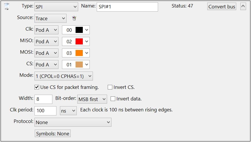
Serial Peripheral Interface (SPI)
|
| |
|
|
| |
|
Select the channels connected to the raw bus signals.
|
| |
|
Warning: DO NOT create duplicate Channel Groups for the serial bus signals! The GoLogic7 software automatically creates a hidden channel group for each signal in the serial bus. If needed, these hidden channel groups can be used to trigger or display the raw signals in the data views.
|
| |
|
When project files are opened, the GoLogic7 software automatically deletes channel groups which duplicate the serial bus channels. This avoid potential conflicts between the channel groups and the serial bus definitions.
|
| |
|
|
| |
|
Select the SPI Mode.
|
| |
|
|
| |
|
When checked, the CS signal defines where packets start and end.
|
| |
|
|
| |
|
When checked, an active-high CS signal indicates packets are active. Normally, the CS signal is active-low.
|
| |
|
|
| |
|
When checked, the bus state is reset if CS signal goes inactive during a data value.
|
| |
|
|
| |
|
Enter the bit-width of each data value.
|
| |
|
|
| |
|
Select the data value bit-order: LSB or MSB first.
|
| |
|
|
| |
|
Inverts the data values.
|
| |
|
|
| |
|
Enter the elapsed time from rising edge to rising edge.
|
| |
|
|
| |
|
The SPI bus is a generic bus with no protocol. The Protocol List allows a Custom Protocol to be applied to the bus data.
|
| |
|
|
| |
|
Click this button to use a Symbol Table with the data values.
|
| |
|
Copyright and trademark information
|

|