|
<< Contents
<< Workbar
<< WorkBar Tabs
<< TRIGGER
<< Serial Bus Trigger
|
| |
|
|
| |
|
The logic analyzer triggers when the packet matches the TriggerForm values.
|
| |
|
Four SDIO trigger types are provided.
|
| |
|
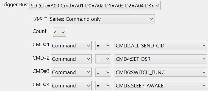
Type = Series: Command Only
|
| |
 |
| |
|
Count
|
| |
|
Select the number of commands in the series.
|
| |
|
The Appendices define each model's trigger limits.
|
| |
|
Direction Bit
|
| |
|
Select "Command", "Response", or "Any".
|
| |
|
Qualifier
|
| |
|
Select the "=" or "!=" qualifier for each command in the series.
|
| |
|
Command
|
| |
|
Select each command in the series.
|
| |
|
The commands available for triggering depends on the Mode option selected in the Serial Tab. The Mode can be SDIO, MMC, or eMMC.
|
| |
|
If commands are missing from the list box, or extra commands are listed, then the wrong Mode option was selected in the serial bus definition.
|
| |
|
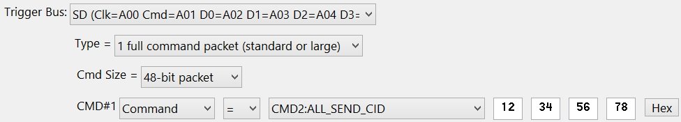
Type = Series: 1 Full Command Packet
|
| |
 |
| |
|
Cmd Size
|
| |
|
Select the "48-bit packet" or "136-bit packet" size.
|
| |
|
Direction Bit
|
| |
|
Select "Command", "Response", or "Any".
|
| |
|
Qualifier
|
| |
|
Select the "=" or "!=" qualifier for the command.
|
| |
|
Command
|
| |
|
Select the command.
|
| |
|
The commands available for triggering depends on the Mode option selected in the Serial Tab. The Mode can be SDIO, MMC, or eMMC.
|
| |
|
If commands are missing from the list box, or extra commands are listed, then the wrong Mode option was selected in the serial bus definition.
|
| |
|
Data
|
| |
|
Enter the command data values. Command data values use the D0 signal in SDR mode.
|
| |
|
Base
|
| |
|
Click the "Hex" or "Binary" button to choose the numeric base for the command data edit boxes. This option is cosmetic and has no affect on the trigger behavior.
|
| |
|
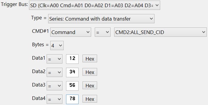
Type = Series: Command With Data Transfer
|
| |
|
| |
|
Direction Bit
|
| |
|
Select "Command", "Response", or "Any".
|
| |
|
Qualifier
|
| |
|
Select the "=" or "!=" qualifier for the command.
|
| |
|
Command
|
| |
|
Select the command.
|
| |
|
The commands available for triggering depends on the Mode option selected in the Serial Tab. The Mode can be SDIO, MMC, or eMMC.
|
| |
|
If commands are missing from the list box, or extra commands are listed, then the wrong Mode option was selected in the serial bus definition.
|
| |
|
Bytes
|
| |
|
Select the number of data transfer bytes.
|
| |
|
The Appendices define each model's trigger limits.
|
| |
|
Data
|
| |
|
Enter the data transfer values. Data transfers use the D0 through D7 signals in either SDR or DDR mode.
|
| |
|
The selected command defines how many Dx signals are used to transfer the data.
|
| |
|
The selected command defines if SDR or DDR mode is used.
|
| |
|
Data transfers are assumed to occur after the command is sent on the CMD signal. The first data byte must occur more than 2 clocks after the end of the command.
|
| |
|
The CMD signal is ignored once the requested command is found and the trigger begins following the data signals. Any number of non-matching commands may occur during the data transfer. Once the command is found, the trigger resets only when a non-matching data value is found.
|
| |
|
Base
|
| |
|
Click the "Hex" or "Binary" button to choose the numeric base for the data transfer edit boxes. This option is cosmetic and has no affect on the trigger behavior.
|
| |
|
Copyright and trademark information
|

|