|
<< Contents
<< Workbar
<< WorkBar Tabs
<< CHANNELS
|
| |
|
|
| |
|
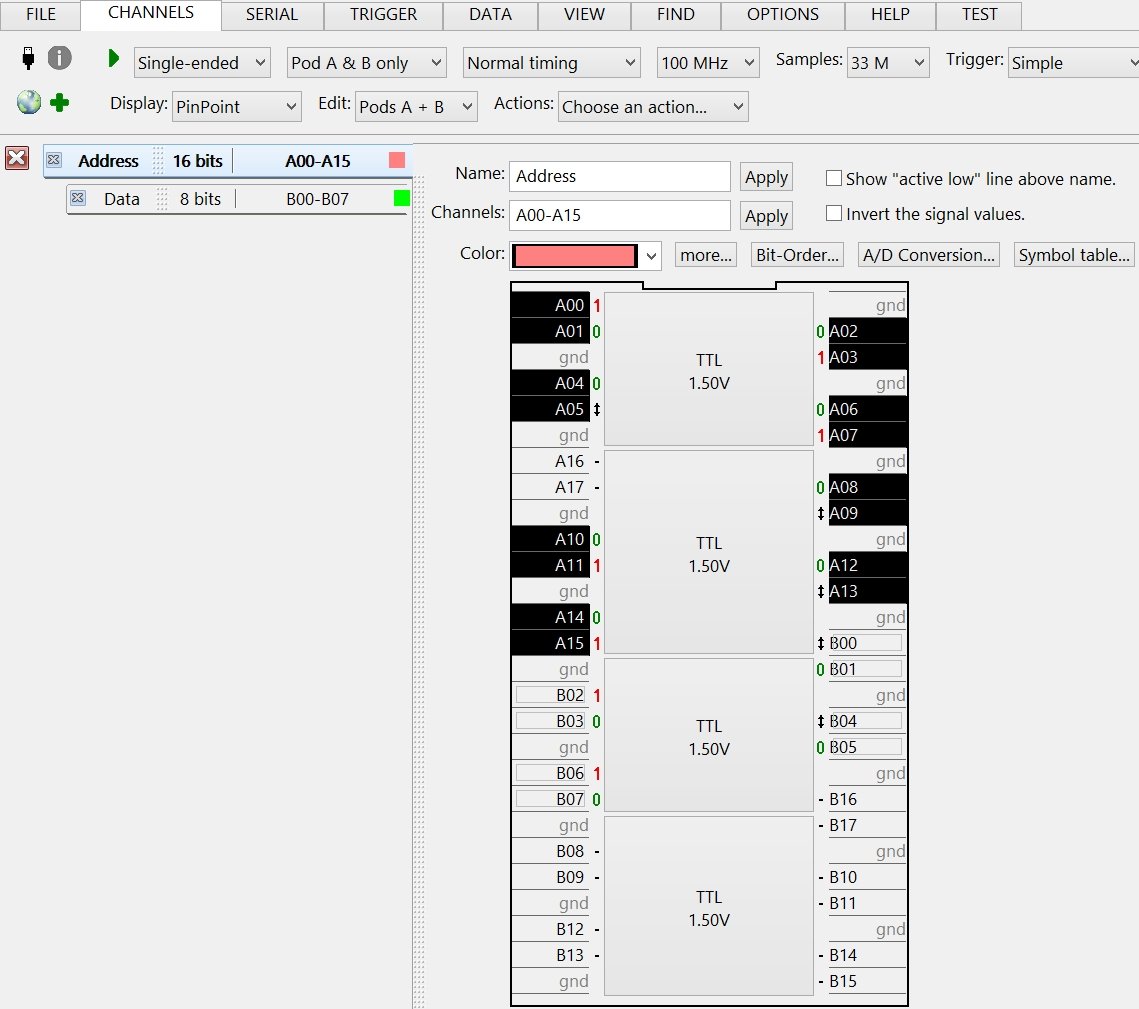
The PinPoint™ Display Type is best used with the PinPoint™ Probes.
|
| |
|
The display mimics a top-down view of the PinPoint™ probe pads integrated into your PCB layout...
|
| |
|
| |
|
|
| |
|
Active Group Tab Area is on the left-side of the PinPoint™ Display Type.
|
| |
|
The active group is edited in the main view area.
|
| |
|
When Transitional Timing mode is active, the Transition Detectors tab is the last tab in the area.
|
| |
|
|
| |
|
The Common Group Edit Controls are above the PinPoint™ diagram.
|
| |
|
Channel Edit Area (PinPoint Diagram)
|
| |
|
Click on the channel numbers to add/remove group channels.
|
| |
|
Each new channel is added as the group's most significant bit.
|
| |
|
Drag the mouse to add/remove multiple channels.
|
| |
|
Drag from top-to-bottom adds new channels in ascending bit-order.
|
| |
|
Drag from bottom-to-top adds new channels in descending bit-order.
|
| |
|
The above example shows the active group using A00 to A15.
|
| |
|
The outline around channels A16 and A17 indicate other groups use those channels.
|
| |
|
The remaining channels are not used in any group.
|
| |
|
Click a Threshold Button to edit the threshold level associated with the channels.
|
| |
|
The Activity Indicators are next to the channels numbers.
|
| |
|
Copyright and trademark information
|

|